After several years of trouble free flying my Electric WOT4 MK2, the inevitable happened...
The ground turned perpendicular to my plane's flight path and rose up to meet it at speed, resulting in the middle 30cm of wing and whole front of the plane being destroyed.
Electronics wise only 1 aileron servo was damaged, which is something I guess.
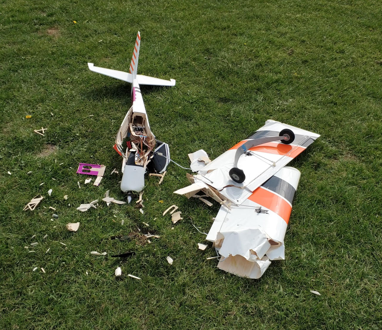
As you can see from the photo, there isn't a lot left of the main fuselage section!
Having established that I'm going to need to re-create the plywood section of the fuselage before building back up with balsa, I decided to use what pieces I had left to create a model of the sides.
This went surprisingly well and with a combination of scans, measuring and luck, I managed to get fairly close to the original.
Note: I took the opportunity to make an integral battery holder platform, so the 2nd bulkhead will not work in an original IC WOT4 MK2.
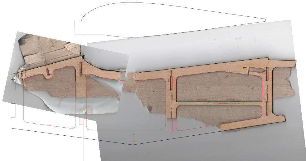
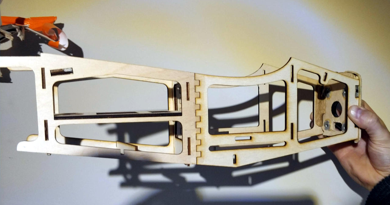
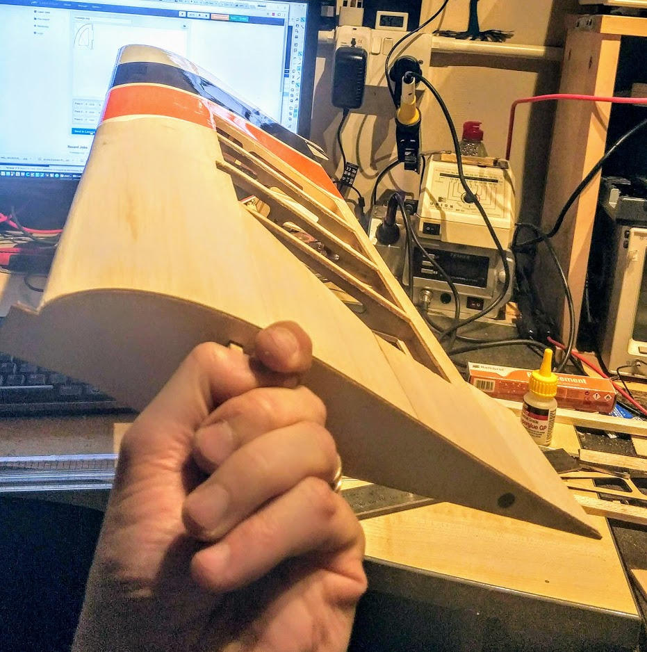
My laser cutter is only A4 so I have had to split the fuselage into 2 sections.
I had some 2.9mm and 3.3mm plywood. The 2.9mm has the grain running the wrong way and snapped too easily. The back piece in this image is 2.9mm, the front is 3.3mm. Although it is heavier, I am using the 3.3mm ply for the sides.
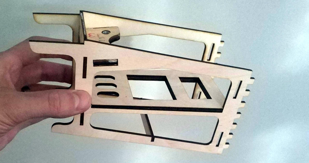
The tooth shapes are an interference fit (read: needs a hammer!), and with some PVA glue make a good strong bond.
Using the original firewall and wing mounting plate (the only surving parts!), I put the cut parts together in a dry fit.
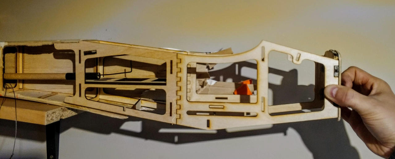
Offering this up to the remaining tail section, I can start to see this might just work :).
I still need to make the 2nd bulkhead / front wing mount upright, but will have to measure this off a friend's WOT4. There was nothing left of it in the wreckage that I brought home!
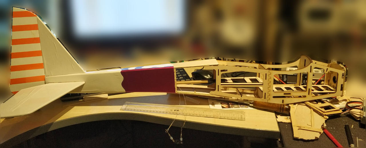
I found a piece of the 2nd bulkhead that gave enough information about the curve and offset to make a replacement. After assembling the remaining parts, I took it to compare against a friend's WOT4. To my amazement, the angles and dimensions are spot on!
I carefully removed the sections of balsa from the tail to leave a good starting point and reference locations for gluing the new fuselage to the tail.
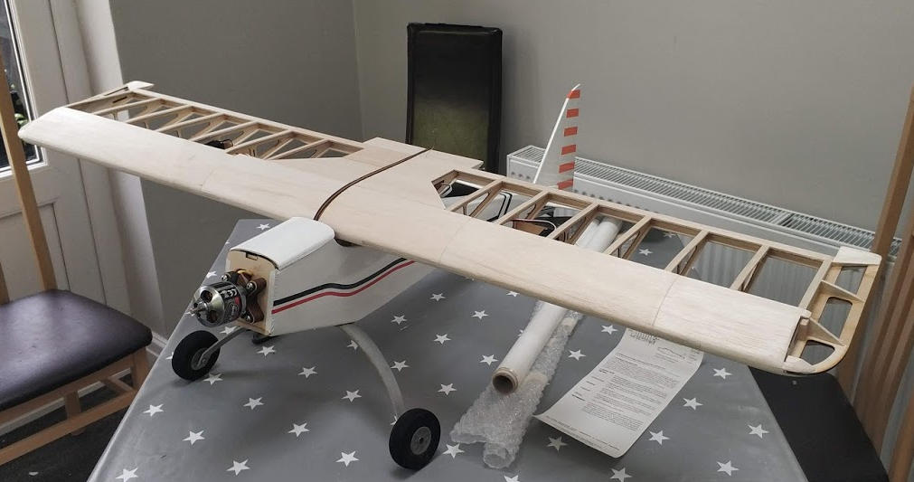
I've ordered balsa for the remainder of the build, which will hopefully be enough to finish the fuselage and the wing.
Having never built a wing before, this task seems somewhat more daunting than the fuselage!
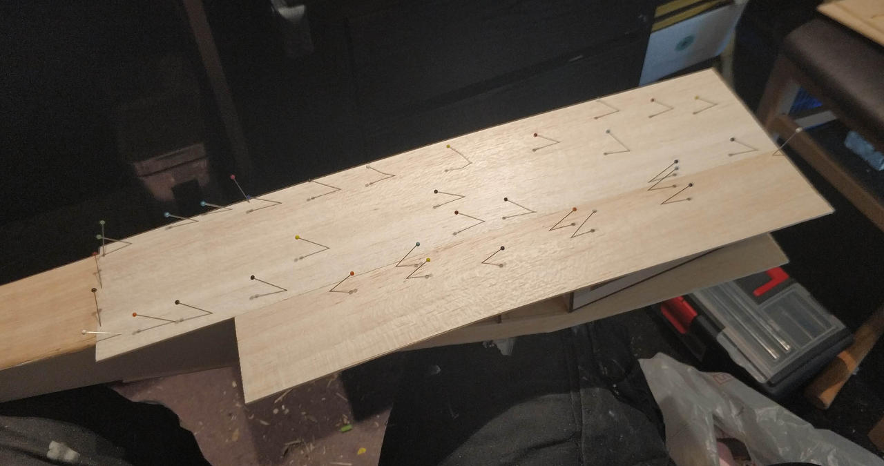
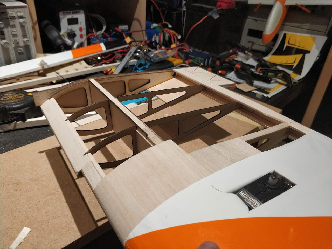
I have created a rib from a salvaged one and the distances between them seems constant. The part I'm most concerned about is how to graft 2 new spars in whilst maintaining their tensional strength...
Starting from a scanned rib, I have extrapolated to the wing root including the mounting tab. This accounts for a 2.4mm balsa covering.
I have also started to model the plywood reinforcement to the spar. This will need to be carefully configured to get the most overlap with the existing wood so the glue can grip with maximum strength.
Time to lean how to glue balsa.
Accupuncture seems to be the way forward.
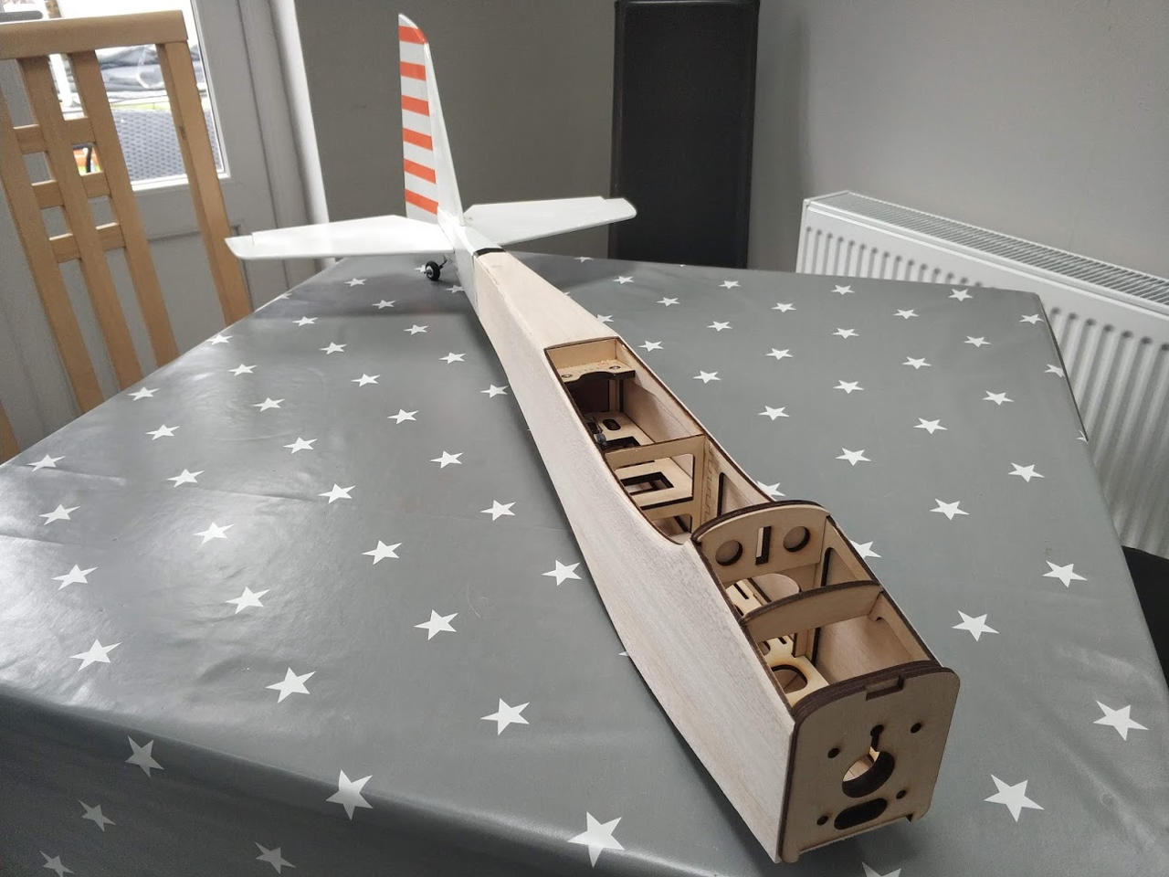
Panelling the fuselage was slow going, but not too challenging. Making sure the last part sets before moving onto the next was the time consuming part.
Sanding the edges was very satisfying and got a really nice finish quickly due to the softness of the wood.
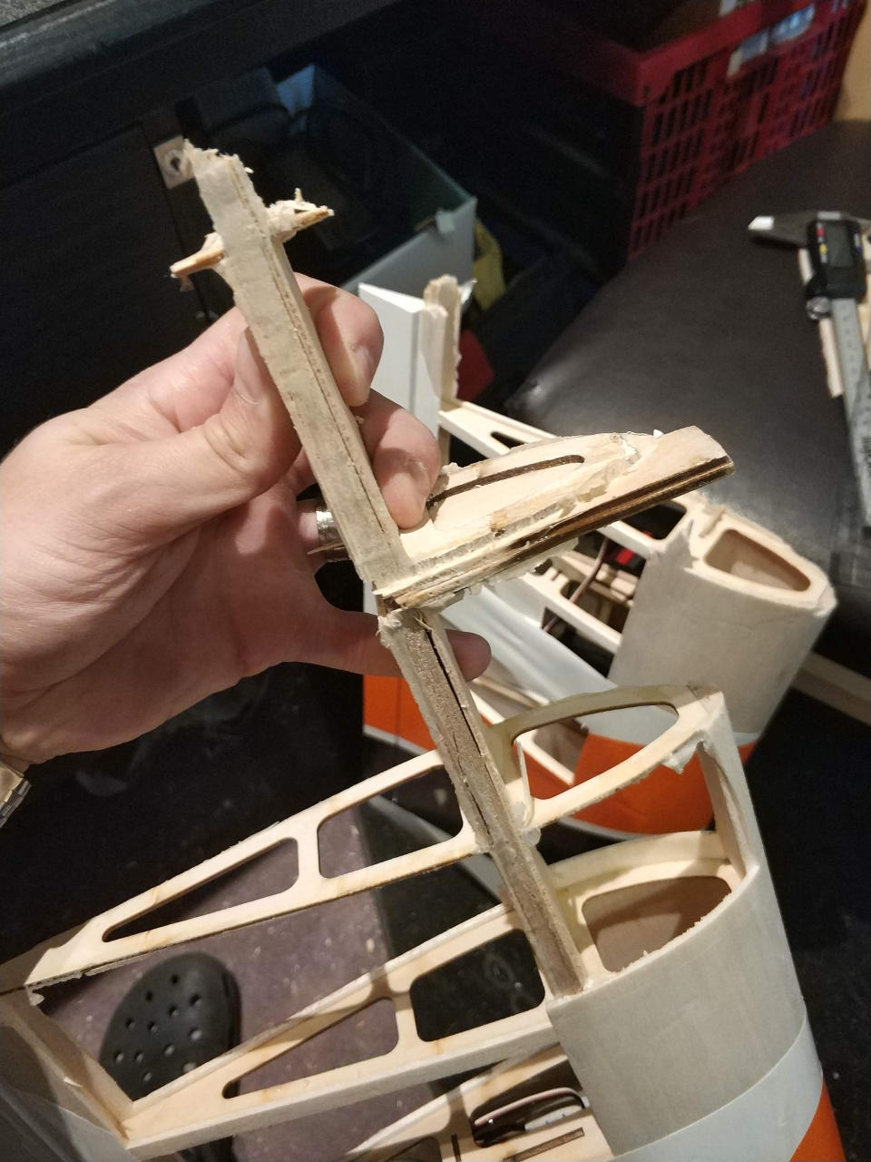
After some research, I think this is the most effective way I can graft the wing spars. It will be strengthened by a rectangle of thin plywood afterwards.
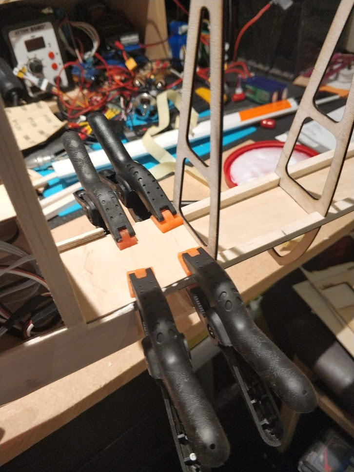
I secured the graft with PVA and plywood on both sides.
This was left clamped overnight to set.
It took most of the morning to get the wing to this point. The trailing and leading edges were an exercise in frustration. I hadn't realised they were knife customised per plane!
The root rib needed a redesign as I has misunderstood how it went together from the small pieces I had.
Amazingly, the wing seems straight and not twisted...
I ran out of balsa cement for building the wings and, being a bank holiday, finding a tube is going to be tricky.
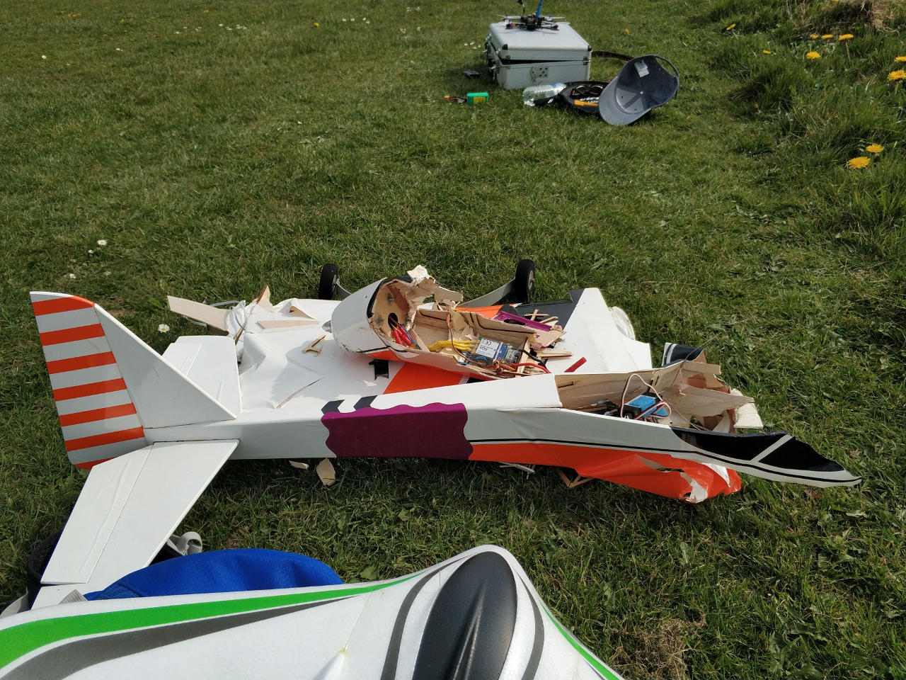
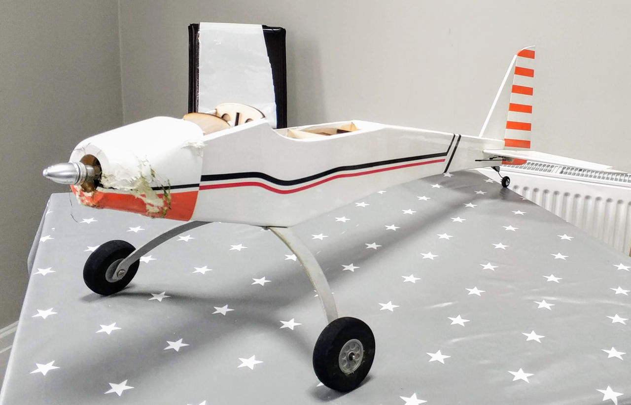
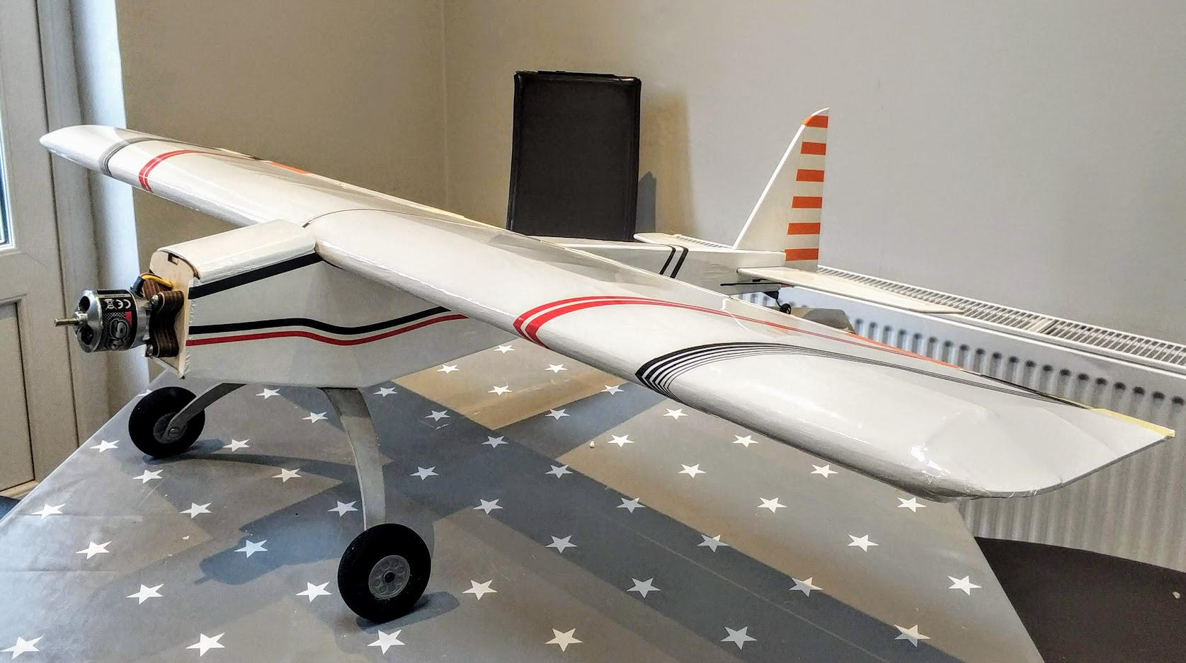
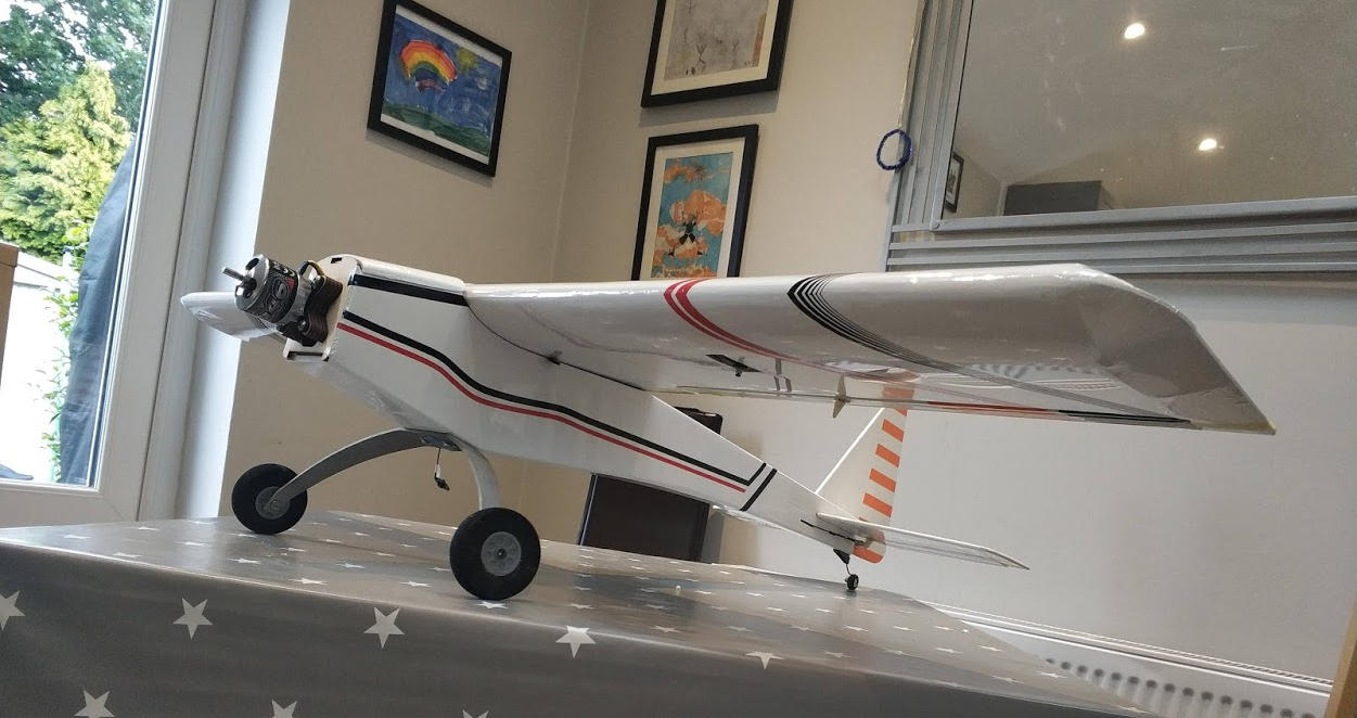
Whilst pondering what to do next, I covered the fuselage and applied some new trim lines. I also discovered that the rudder servo has gone short circuit, so will need another one.
The nose cowl is going to be replaced, so don't worry about the mismatched trim and pieces of grass! :)
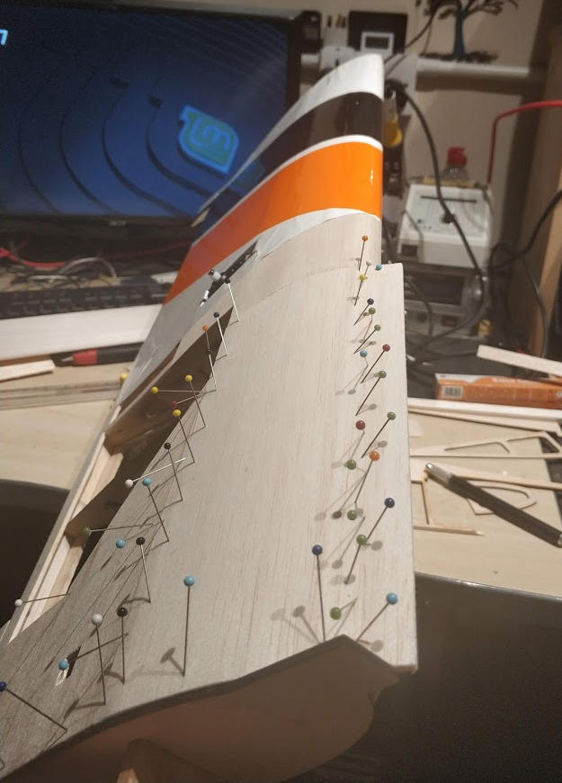
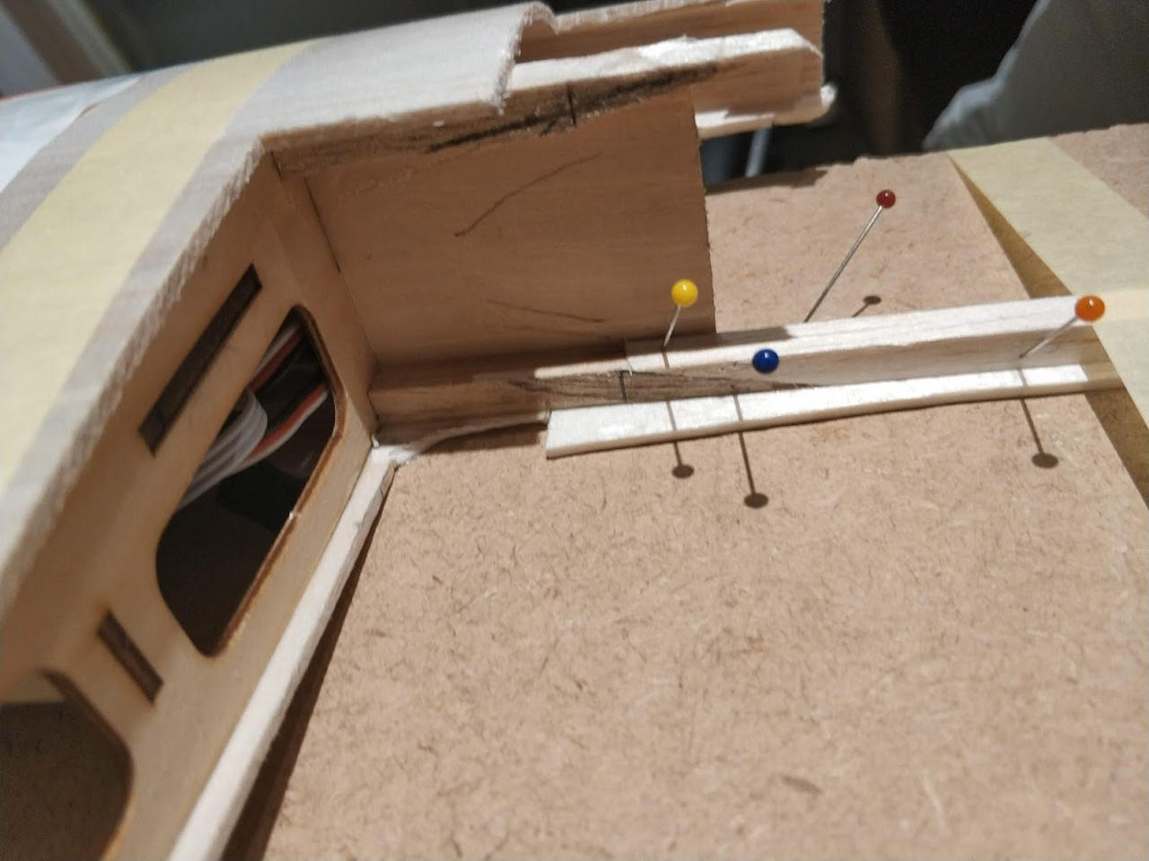
Gluing the leading edge with Cyano Acrylate was easier than I had expected. Because the angle isn't too steep, there is not too much pressure on the balsa when curving it around.
I have however learned the difference between C grain balsa and normal balsa sheet... C is stiffer and snaps when curving it :).
Working the balsa with a knife and sand paper is quickly rewarding; however the dust and mess is horrendous.
I mentioned that the root rib needed a slight redesign. That involved making the rear taper 10mm longer and coming down to a slightly finer point. Unfortunately, the fuselage cabin was modelled from my original root rib model.
Long story short: the fuselage is 10mm too short and the rear of the wing hangs over the rear of the cabin slightly. Not the end of the world, but annoying!
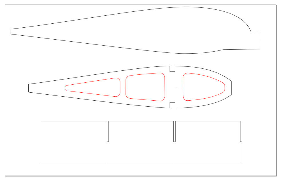
The .svg below has the corrected version implemented.
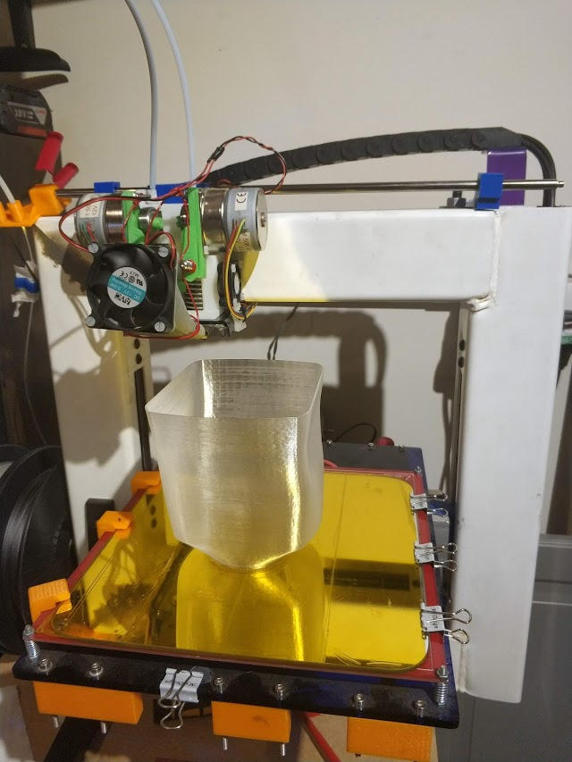
My 3D printer normally has a 0.4mm nozzle. For the nose cone / cowl I needed a much thicker wall and didn't want to wait forever for the normal print.
I swapped the 2nd extruder nozzle for a 1mm version and used some flexible filament. This worked really well and has produced a strong but semi-flexible cowl that only took an hour to print in vase mode (1mm wall thickness, 0.3mm layer height).