I have had a proprietary CC2500 based 2.4GHz smart heating system for many years now, but updating it is hard work and the reception is not great. Wouldn't it be nice to convert to WiFi...
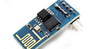
Enter the ESP8266 and a quick test project to see if the module meets my requirements.
The ESP8266 is a low power, low cost, WiFi module that can have custom firmware compiled and flashed into it. There is a community of developers out there and a nice SDK for development. The Wiki

Energy meters that I have used in the past had a ferrite core that clipped around the mains electrical inlet to my house. A quick search on banggood.com revealed that they're cheap and easily available!
I found this very well written page that described exactly how to interface with an arduino. I made some slight changes to the values (the ESP8266 needs 0-1V on the ADC input) and knocked up a circuit.
To my delight the values from the ADC were pretty accurate to within 50W of what my socket meter reads. I used a modified extension lead and a 3KW oil filled radiator to experiment.
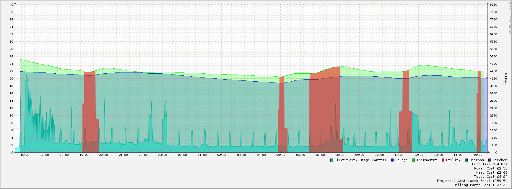
I hacked up a bit of code to receive the UDP packet (Power usage in Watts) from the ESP8266 and feed it into my heating monitor. It was working well and I could see when my wife put the kettle on!
Concept proved, time to make it neat and tidy.
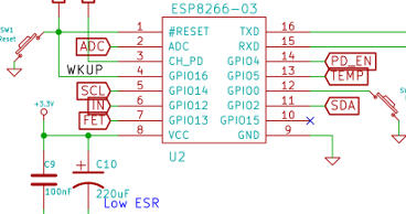
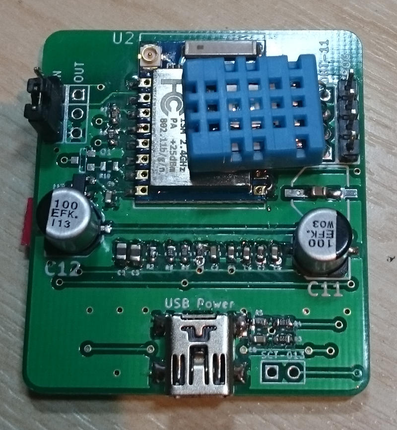
I fired up my trusty KiCAD package and captured a schematic for the ESP-03 module. I have included the necessary connections for 70uA low power mode, DHT-11 temperature sensor, AUX in and out, plus buttons to make flashing and user input easier. Power is via a miniUSB connector (I didn't have any microUSB ones)
I have other projects that use the 128x64 I2C OLED display and figured it would make a nice optional addition to this project.
I'm very pleased with the PCBs. SeeedStudio have excelled themselves again.
I went for a rounded edge on the PCB, which has come out well and they work perfectly.
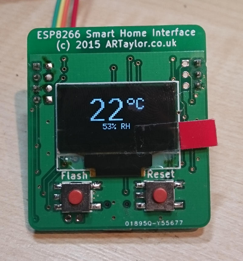
Total system current is 56uA with LCD and ESP8266 in deep sleep, so should be good for periodic wakeups.
Now... If only I had some NVRAM whilst in sleep mode!